Производительность и напор смешаннопоточного насоса HW находятся в диапазоне значений, характерных как для центробежных, так и для осевых насосов. Он отличается компактными размерами, небольшим весом, высоким КПД с широким диапазоном эффективной работы, простой конструкцией, удобством эксплуатации и легкостью технического обслуживания. Он подходит для перекачки чистой воды или других жидкостей, схожих с чистой водой, и широко используется для орошения и дренажа сельскохозяйственных угодий, а также для промышленного водоснабжения и водоотведения.
Применение смешаннопоточного насоса HW
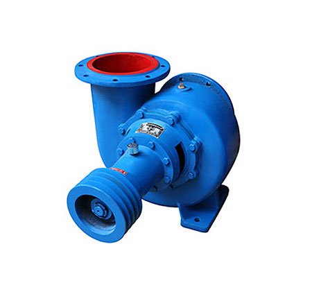
Насос HW представляет собой горизонтальный односторонне всасывающий спиральный насос смешанного типа. Он предназначен для перекачки чистой воды или других жидкостей, физико-химические свойства которых аналогичны свойствам воды. Насос широко применяется в орошении и осушении сельскохозяйственных угодий, промышленном водоснабжении и водоотведении, городском водоснабжении и водоотведении, а также в других областях.
Смешаннопоточный насос HW представляет собой усовершенствованную модель, разработанную совместно предприятиями насосостроительной отрасли Китая, и является энергосберегающим изделием, продвигаемым и применяемым машиностроительной отраслью Китая.
Характеристики аппаратного насоса смешанного типа
Диапазон производительности:
Расход: 180–3665 м³/ч
Высота: 3,0–20,7 м
Мощность: 3–250 кВт
III. Описание смешанного насоса HW
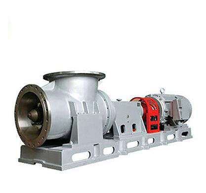
Особенности: простая конструкция, надежная работа, удобство монтажа и технического обслуживания, высокая эффективность, компактные размеры и небольшой вес.
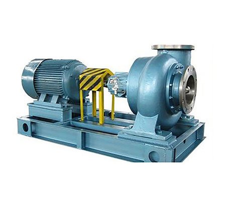
Типы привода: прямой привод и привод с регулируемой скоростью. В качестве приводных механизмов обычно используются электродвигатели и дизельные двигатели. Тип (мощность, скорость) приводного механизма необходимо указать при заказе для определения технических характеристик муфты и шкива.
Направление вращения. Если смотреть со стороны входа насоса, рабочее колесо, как правило, вращается против часовой стрелки (модели 650HW-5, 650HW-7 и 650HW-10 вращаются по часовой стрелке).
Описание конструкции смешанного насоса HW
Пример: 300HW-7S
300: Диаметр впускного и выпускного отверстий насоса (мм)
HW: Спиральный насос смешанного типа
7: Расчетный напор насоса (м)
S: Тип конструкции (конструкция передней и задней дверей)
Принятые стандарты
Насос HW-S разработан, изготовлен и прошел проверку в соответствии со стандартами GB/T 13008 и JB/T 6667.
Конструкция и применение смешаннопоточного насоса HW
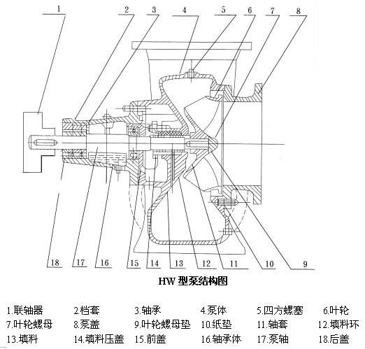
Насосы типов HW и HB в основном состоят из крышки насоса, рабочего колеса, корпуса насоса, вала насоса, втулки вала, корпуса подшипника (для диаметра отверстия ≤ 350 мм) или подшипникового кронштейна (для диаметра отверстия ≥ 400 мм) и других основных компонентов.
Крышка насоса соединяется с корпусом насоса и впускным трубопроводом соответственно. Между торцевой поверхностью крышки насоса и торцевой поверхностью рабочего колеса должен поддерживаться надлежащий зазор. Слишком малый зазор приведет к трению; слишком большой зазор вызовет значительный обратный поток воды под давлением внутри корпуса насоса, что снизит КПД насоса.Рекомендуемый практический зазор составляет 0,3–0,7 мм (при смещении вала насоса в сторону входа насоса). Зазор можно отрегулировать, увеличив или уменьшив толщину бумажных прокладок.
Уплотнительный узел вала состоит из сальника, сальникового кольца и сальниковой коробки на корпусе насоса (насосы моделей 150HW и 200HW не оснащены сальниковыми кольцами). Его назначение — предотвратить попадание воздуха в насос и чрезмерную утечку воды вдоль вала.
Втулка вала служит для защиты вала насоса и при износе может быть оперативно заменена.
Вал насоса опирается на однорядные радиальные шарикоподшипники. Подшипники можно смазывать смазочным маслом — уровень масла следует поддерживать в пределах меток на масляном датчике; либо смазывать консистентной смазкой, которую можно заправить при сборке насоса и доливать во время эксплуатации, сняв переднюю и заднюю крышки.
Резьбовое отверстие в верхней части корпуса насоса предназначено для всасывания жидкости или подключения вакуумного насоса для откачки и всасывания жидкости.
Для расширения спектра применения и удовлетворения различных требований пользователей можно изменить внешний диаметр рабочего колеса или заменить его на рабочие колеса с другими характеристиками (обозначенные буквой “A” и т. д.).
К аксессуарам для насосов типов HW и HB относятся колена, донные клапаны, шкивы или муфты и т. д.