The HLC vertical long-shaft pump is an advanced and mature series developed by absorbing domestic and foreign advanced design and manufacturing experience, combined with market demands.
It is suitable for conveying clean water, sewage containing a certain amount of solid particles (such as iron scraps, sand, coal powder), corrosive industrial wastewater and seawater. The temperature of conveyed liquid shall not exceed 80℃.
It is widely applied in raw water treatment plants, sewage treatment plants, metallurgy and iron & steel industry (especially for scale removal water transportation in swirl ponds of this industry), power plants, mines, municipal engineering and farmland water conservancy projects.
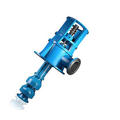
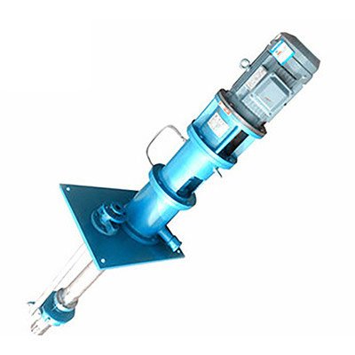
Structural Features of HLC Long‑shaft Multistage Submerged Pump
The HLC vertical long‑shaft pump features a vertically downward inlet and horizontal outlet. It is installed on a single foundation and directly coupled with the motor. Viewed from the top of the motor end, the pump rotates counterclockwise. Its main characteristics are as follows:
-
Optimized by hydraulic design software, the pump delivers superior performance. The abrasion and corrosion resistance of impellers and guide vanes are fully considered, greatly extending the service life of vulnerable parts such as impellers. The equipment operates stably, safely, reliably, with high efficiency and low energy consumption.
-
A filter screen is installed at the pump inlet with properly sized openings. It effectively prevents large impurities from entering and damaging the pump, while ensuring the inlet flow area is more than 3.5 times the cross‑sectional area of the lift pipe, reducing inlet pressure loss and improving pump efficiency.
-
Balance holes are adopted on the impeller to balance axial force. Replaceable wear rings are arranged on both the front and rear shrouds of the impeller to protect the impeller and pump casing. The wear rings adopt a special weir‑type structure, which effectively avoids the deposition of iron scale and other impurities at the ring clearance after shutdown, significantly prolonging the service life of wear rings and impellers.
-
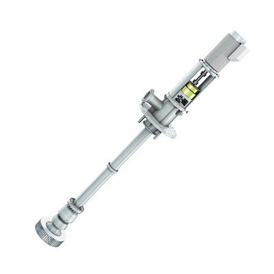
The intermediate shafts, lift pipes and protective pipes are of multi‑section structure. Sleeve coupling is applied to intermediate connecting shafts, improving radial concentricity by ten times compared with other coupling forms and reducing overall unit vibration by over 70%. The number of lift pipes can be increased or decreased to adapt to different submerged depths. Multistage impellers and guide vane assemblies are optional to meet various head requirements.
-
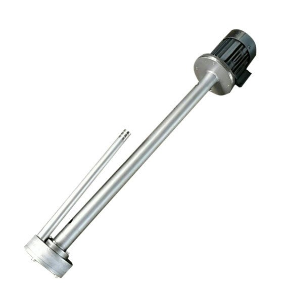
The lift pipes are connected by flanges, with guide bearings arranged in the middle. Guide bearings are made of reinforced filled PTFE or Canadian Celeron materials; nitrile rubber is optional for medium temperatures above 55 ℃. The shaft is protected by a protective pipe.
- For clean water delivery: The protective pipe can be omitted, and no external cooling/lubricating water is required for guide bearings.
- For sewage delivery: External cooling and lubricating water is mandatory for guide bearings.
For sites lacking clean water or with high water costs, a special auxiliary structure can be equipped. The pumped medium, after filtration and sedimentation separation, can be used for guide bearing cooling and lubrication.
The lubrication water system can be fitted with flow and pressure relays. The pump cannot start if the water supply is lower than the rated flow before operation. In case of water shortage or pressure loss caused by pipeline blockage during operation, the relay triggers an alarm with buzzer and red warning light in the control room. Operators can open the bypass valve to ensure sufficient water supply and conduct troubleshooting. This control system supports remote operation.
-
The residual axial force and the weight of the rotor assembly are borne by the thrust bearing inside the motor base or by a motor equipped with an integrated thrust bearing. The thrust bearing adopts thin oil lubrication with external water cooling, and can be embedded with temperature sensing elements.
-
The pump adopts packing sealing for shaft sealing. Replaceable shaft sleeves are installed at the shaft seal and guide bearing positions to protect the main shaft. The axial position of the impeller can be conveniently adjusted via the adjusting nut on the upper part of the bearing assembly or inside the pump coupling.
-
The pump can be equipped with a control cabinet, supporting liquid‑level automatic start/stop, overload alarm, real‑time remote monitoring and other functions, and realizing multi‑pump networked centralized remote control. Pumps with a diameter larger than 500 mm are equipped with an automatic exhaust system.